


Introduction
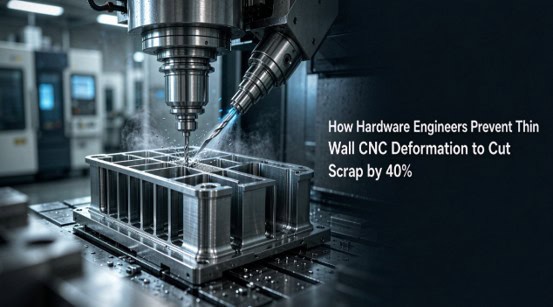
Lightweight aerospace and small-scale electronics design parts to their physical minimums of 0.5 mm, sometimes even under 0.2 mm. Cutting forces cause these thin-walled components to be lacking in rigidity and thus generate chatter, push-off, and warpage, resulting in scrap levels above 30%.
This issue is caused by the concentration of cutting forces, heat distribution, and non-uniformity of residual stresses relieved in the process of clamping. In this paper, we investigate the minimum wall thickness, multi-operation avoidance, five-axis milling paths, and tolerance zones defined according to ASME Y14.5.
What Are the Critical Minimum Wall Thickness Rules for Precision CNC Milling?
There is a floor to every material’s thickness.
Metal and Polymer Thickness Boundaries
6061-T6 and 7075-T651 support 0.8 mm unsupported and 0.5 mm supported; Ti-6Al-4V and 304/316L require 1.0 mm minimum wall thicknesses, while POM, ABS, and PEEK have 0.5-0.8 mm minimum wall thicknesses with cooling. Those aiming for precision thin wall machining treat these minimum wall thickness CNC floors as inputs.
Aspect Ratio and Pre-Compensated Deflection
The stiffness drops by the cubic power beyond 10:1 ratio between height and thickness. This custom thin wall CNC machining guide highlights the DFM pre-compensation for deflection up to 0.02-0.05 mm for custom thin wall CNC parts; CNC minimum wall thickness rules make this rule quoteable.
Why Do Thin Wall Components Deform During High-Speed CNC Machining?
The three methods coincide at below 1.0 mm level; CNC thin wall deformation control resolves all.
Transient Deflection and Thermal Gradient
Radial force causes elastic deflection of the wall and releases it after the tool moves, whereas thermal force makes it bend. Titanium increases both: 6.7 W/m·K retains heat, and low modulus increases spring-back.

Residual Stress Release and Material Contrast
Residual stress distribution changes once 70% of the billet is consumed. Aluminum spring-back contrasts with titanium conductivity. So aluminum and titanium thin wall machining require different windows; thin wall deformation control distinguishes roughing, stress relief, and finishing.
Data sources and benchmarks: ASM International Metals Handbook (Volume 16: machining heat transfer and residual stress relief behavior models).
How Can Advanced Toolpath Strategies and 5-Axis Machining Minimize Dynamic Cutting Stress?
Toolpath is the most economical lever to use.
- Climb Milling, Step-Down and Trochoidal Contro: The reciprocating roughing impacts the wall through reverse force vector application, and climb milling loads material into bulk. The trochoidal approach controls forces within ±10%, preventing any vibration.
- Shortening Tool Overhang on Five Axes: 5-axis thin wall machining moves the workpiece so that the shorter tool can access the wall, keeping the ratio at ≤3:1. Thin wall CNC machining in five-axis maintains engagement; precise CNC rapid prototyping confirms geometry.
Data Sources and Benchmarks: Sandvik Coromant trochoidal milling cutting dynamics test white paper for aerospace thin wall structures (tool vibration acceleration and surface waviness PSD analysis).

What Specialized Workholding and Fixture Designs Prevent Clamping Distortion?
The clamping force determines whether the wall will be held up or smashed.
Why Rigid Vise Jaws Fail Thin Walls
Concentrated forces from vise contact exceed the yield strength of a cross-section; the walls get deformed and rebound. Soft jaws distribute forces, but this approach does not always work for walls thinner than 1.0 mm.
Vacuum, Low-Melt Alloy and Phase-Change Support
The vacuum chuck pulls the bottom face against the sealed surface; it provides uniform forces and damping action; pockets of low-melt alloy or wax melt after holding the walls. A thin wall parts manufacturer combines both for precision thin wall machining and low-volume CNC production.
Data sources and benchmarks: Hydraulic conformal fixture engineering application specification for flexible thin wall parts (clamping strain finite element validation model) SME (Society of Manufacturing Engineers).
How Do Tight Tolerance Guides and CMM Inspection Ensure Quality Compliance?
Study the free body, not the clamped one.
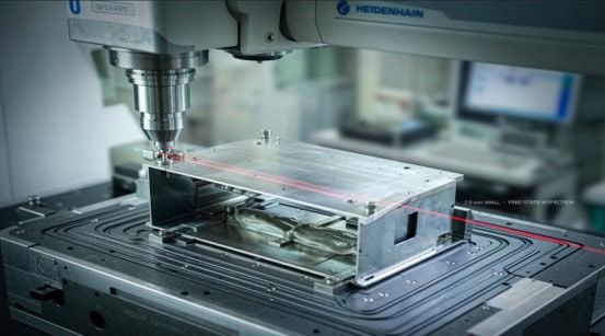
- Allocating Flatness, Profile and True Position: Since ISO 2768 tolerances are too generous, therefore it’s necessary to assign tolerances for flatness, profile and true position. ISO 10360-2 determines criteria for CMM acceptance and re-verification and makes auditing defensible; CNC machining tolerance guide allocates tolerance by function.
- Non-Contact Measurement Under Controlled Temperature: Contact probes deflect a 0.5 mm wall, therefore CMM laser scanning uses non-contact measurement. 20°C ±0.5°C temperature eliminates growth effect. On CNC thin wall quote, make sure that record shipped, because custom thin wall CNC parts without records can’t be verified.
Data Sources and Standards: Zeiss CMM official calibration report (measurement accuracy 0.0009 mm and MPEE volumetric indication error) and ISO 10360-2 acceptance criteria for coordinate measuring machines.
What Factors Dictate Thin Wall CNC Machining Cost and Manufacturing Efficiency?
Thin wall CNC machining cost is related to risk rather than material cost.
The Cost Model Behind Thin Wall Parts
Material consumption, machine hourly rate, annealing, and test cuts contribute to the thin wall CNC machining cost, and slow feed rate extends cycle time. Tiered pricing indicates fixture depreciation as the major cost driver for small volumes; thin walls double the unit cost.
From Prototype to Stable Low-Volume Output
Low-volume CNC production implies fixing the fixture and pass sequence, which can be certified by a CNC thin wall machining service. A reputable online CNC machining service automates the thickness inspection; LS Manufacturing provides DFM and deformation information in 2 hours.
Data Sources: Haizol 2026 China precision CNC machining tiered pricing white paper (cost calculation model of pneumatic fixture amortization and multi-operation cost distribution).
Conclusion
Thin wall metal and plastic milling is difficult. The elimination of warpage requires a closed feedback loop that incorporates design for manufacture rules for stress relief via low stress machining and fixture conformality, as well as non-contact measurement, and not experience. DFM rules eliminate unplanned scrap by 40% and more.
FAQs
Q1: What is the absolute minimum wall thickness achievable in CNC milled aluminum components?
A: The lowest possible value is 0.8 mm for unsupported vertical walls, whereas for supported pockets it can be as low as 0.5 mm. When using specialized five-axis machines, high-speed micro-end milling may allow creating vertical walls with 0.3 mm thick for pockets up to 20 mm in height and with tolerance of ±0.025 mm.
Q2: Why does titanium alloy require different thin wall cutting parameters compared to aluminum?
A: Titanium has very low thermal conductivity (only 6.7 W/m·K), and also its elastic modulus is rather low, which means that heat concentration occurs near the cutting point and there is significant spring-back against tool flanks. To avoid chatter, cutting speed should not exceed 60 m/min and high-pressure coolant (not less than 70 bars) and micro-grain carbide tools should be used.
Q3: How do specialized vacuum chucks prevent deformation during thin plate face milling?
A: Conventional clamping through vises results in upward bowing since there is an asymmetrical transverse mechanical stress applied. The vacuum fixture applies clamping forces evenly to the whole bottom surface by means of special elastomeric sealing channels. Thus, there will be no clamping stresses in particular spots, vibration suppression and, at the same time, the flatness level will be maintained not higher than 0.015mm on large surfaces (>=300mm x 300mm).
Q4: When should engineers mandate stress relief heat treatment for custom thin wall components?
A: Stress relief annealing is mandatory when the percentage of material that needs to be machined exceeds 70% of the volume of the initial billet or when the wall thickness is less than 1.0 mm after machining. Intermediate thermal treatment cycles (like keeping the AL 7075 part at 150°C for two hours before finishing machining) remove residual stresses so that any subsequent deformation becomes impossible during the whole life of the part.
Q5: Can thin wall CNC machining maintain aerospace-grade dimensional tolerances without secondary grinding?
Q: Yes. Through high-speed five-axis simultaneous milling, along with balance semi-finishing machining, today’s machining cells have the ability to manufacture parts in tolerance according to ISO 2768-f straight from the raw stock material. Laser tool set-up within the process and touch trigger probing ensure wall thickness accuracy of ±0.012 mm, as well as surface roughness Ra ≤0.8 μm without abrasives.
Author Bio
Gloria is a writer for LS Manufacturing, a company offering solutions for innovators with thin wall challenges. LS Manufacturing has been certified to ISO 9001, ISO 14001, IATF 16949 and AS9100D. The team will deliver audited process control, not just promises. Upload your 3D CAD files. Contact us for a free DFM analysis.