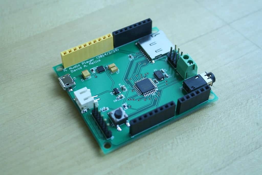
I recently decided that I was going to try my hands on PCB (printed circuit board), and it was a worthwhile experience. For the less techy friends, a Printed Circuit Board is made from reinforced phenolic resin that has been bonded with copper foil. The printed circuits themselves are made from copper, which is plated on the surface of the board to give it a cool pattern.
You’d find this in virtually all electronic gadgets, either industrial or domestic. It gives mechanical support to the electrical connections on it. To use the PCB for your idea, you’d need a good knowledge of CAD, you’d also need a good PCB design software which will practically take your design and print it in the board.
I created my PCB designs manually, but it’s also possible to do it automatically. Manually, I had to use CAD drafting, using the automatic router to create the designs. I have tried both manual and automatic designs, but for this project, I decided to go with what many designers use, which is the manual way of designing the PCB.
If you have not created an assembly schema yet, you only need to know the different elements of an assembly schema and know how your PCB routing tools can help you create this schematic.
Many years ago, I had to use a separate design tool to create assembly drawings. In fact, the old PCB routing systems I was using at the time did not allow us to create the detailed schematics we needed. Today’s routing tools now have the functionality to create your assembly drawings. Here are three tips I just learned, which will be helpful on your next project.
- Map outlines with component information can be imported, resized, rotated, and reflected if the schema requires it.
- Assembly instructions can be generated or imported from an external file and then added to the schema.
- Detailed cutout views of sensitive areas of the assembly can be detached and enlarged once completed.
Unlike parents who “do not see clearly and get lost in the assembly instructions after eleven hours of hard work,” you can help your manufacturer by creating a clear and informative assembly diagram for your circuit board.
With this diagram, you can guarantee to your manufacturer that the PCB of your printed circuit will be carried out correctly and without delay.
Do your CAD tools allow you to easily and quickly create assembly drawings? I use RayMing PCB Assembly since it basically makes my life easier by removing most of the hard work when creating my assembly designs.
You can also pay a draftsman to help you create an assembly diagram that your manufacturer will be happy to use.
Whichever you decide to do, an advice I always give is that you should learn to make these assembly diagrams yourself. It’ll help you use the right tools and it’ll also save money as you would know just how much a draftsman who would do it for you should charge.


